Improvising a 555 timer using an ATTiny85
In short, I needed a 1Hz timer for a shift register project and didn’t have any timing ICs around, so I improvised using an ATTINY85. The datasheet 1 in section 12.2.2 says that Timer/Counter1 can be used in PWM mode with two outputs, one normal and one inverted:
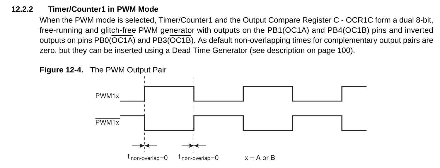
Figure 1 - Timer1 in PWM mode with output pairs.
This was exactly what I needed for clocking the shift register I was using (74HC595) that had shift and storage clocks.
#define F_CPU 1000000UL

#include <avr/io.h>

static void ConfigurePWM( void )
{
    /* Reset counter */
    TCCR1 = 0U;

    /* PB4 = PWM output, PB3 = PWM inverted output */
    DDRB |= ( 1U << 4U );
    DDRB |= ( 1U << 3U );

    /* Clear timer on compare match,
     * PWMA enable,
     * Toggle OC1A output line,
     * Precale clock CK/8192
     */
    TCCR1 = 0xDE;

    /* PWMB enable,
     * Toggle OC1B output line
     */
    GTCCR = 0x50;

    /* 1MHz / 8192 / 122 ~= 1Hz */
    OCR1A = 61U;
    OCR1B = 61U;
    OCR1C = 122U;
}

void main( void )
{
    ConfigurePWM();
    while( 1 );
}
Using a logic analyser this is what it looks like on the output:
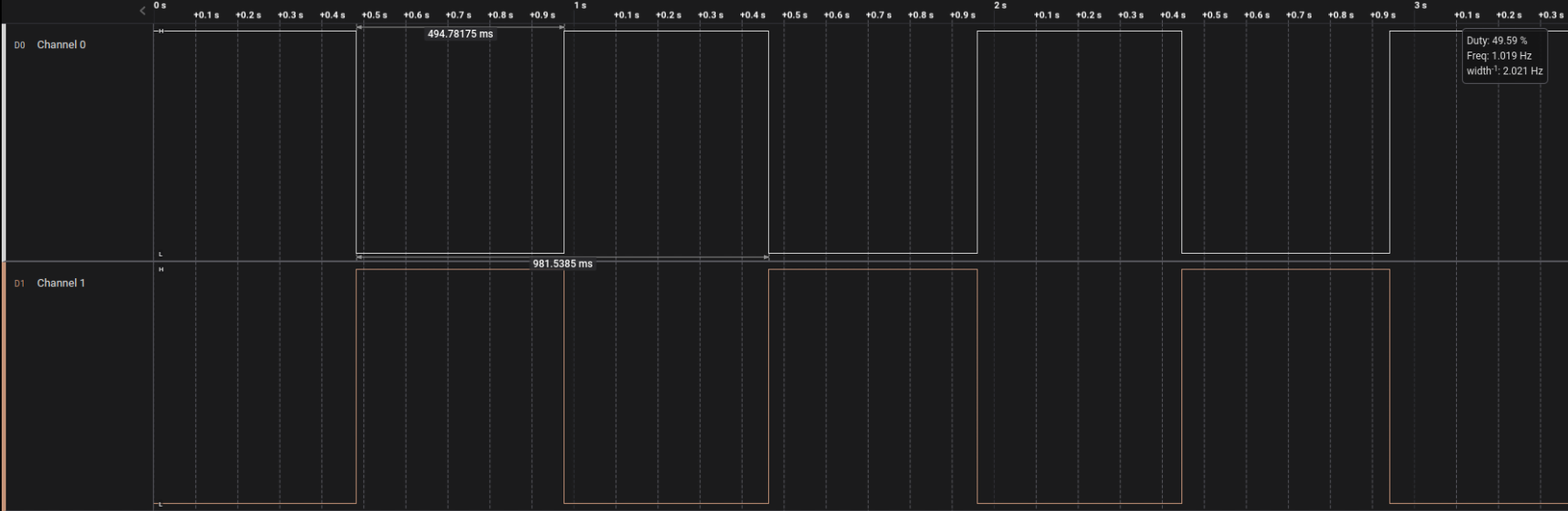
Figure 2 - Logic analyzer output from the ATTiny85 connected to PB3 and PB4 displaying a 1Hz signal