microboids
I previously wrote about implementing the boids algorithm in Rust so that it runs on a desktop computer. The result is an aesthetically pleasing simulation of a bird murmuration. I got a small 800x480 LCD display for a Raspberry Pi 3B+ I had lying around with the intention of making a little shelf ornament running the simulation. Upon running the code I found that the performance was suboptimal, even after significantly reducing the number of birds in the model. It came as no surprise given that all the maths was implemented using floats. Nonetheless I was determined to have my shelf ornament so I decided to rewrite the whole thing in C using fixed-point maths so that it would not only run on the Raspberry Pi, but also a tiny M0+ microcontroller connected to an SSD1306 OLED display. Given that this is a bare metal implementation, this would also involve rewriting the trigonometry functions, which I’ve discussed briefly below.

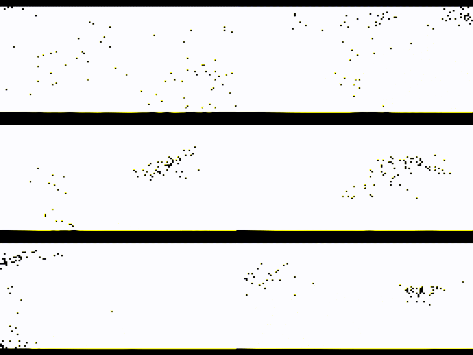
Desktop simulation of microboids using entirely fixed point arithmetic
In order to speed up the development I implemented a very basic simulator for an LCD display which can display the murmuration as if it was running on a hardware target. The full source along with makefiles can be found here

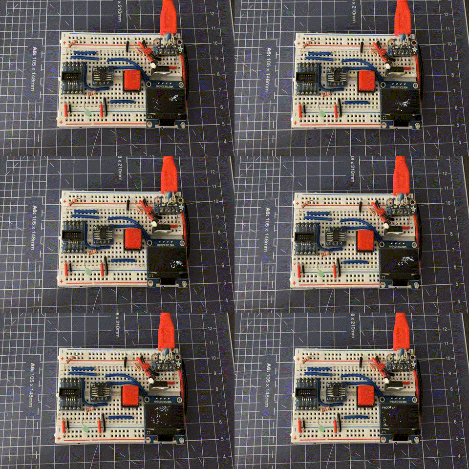
microboids running on an ARM M0+ Microcontroller (64MHz, STM32G031J6)
The bare metal code for running on target can be found here but there is no documentation so there be dragons!
Fixed Point 101
The maths was implemented using Q Arithmetic1 which is the technique used to represent floating point numbers using integers. There’s a really handy ARM manual floating2,3 around explaining how it works as well as some example code for implementing the various operations. I decided to use Q15, which means there are 15 bits of precision with the MSB being a sign bit (assuming 16 bit integers). This allows representation between [-1,1), where -1 = 0x8000 and 0.99997 = 0x7FFF. The ARM fixed point maths manual provides some useful example code for converting between floats and Q format2:
#include <stdint.h>
typedef float float32_t;

#define FLOAT_TO_Q(X, Q) (int16_t)((X) * (float32_t)(1 << (Q)))
#define Q_TO_FLOAT(X, Q) (float32_t)((X) / (float32_t)(1 << (Q)))
I found a handy calculator for converting between decimal and Q arithmetic which you can find here4. I implemented functions for Multiply, Add and Subtract based on 1 and 2 which can be found here. The Add and Subtract functions implement saturation to prevent signed integer overflow/underflow which is Undefined Behaviour5.
Implementation considerations
- The screen is now represented in the range
[-1,1)using Q15 arithmetic- Can be converted to pixel co-ordinates for writing to the display
- Could be represented using Q31 with minimal changes
/*
 * Struct representing the pixel co-ordinates in the 2D space
 * using Q15 arithmetic
 */
typedef struct
{
    int16_t x;
    int16_t y;
}
pointf16_t;- Sine and Cosine replaced with look up table (LUT)
sinandcosnecessary for moving the bird with respect to itsangle- Minimal memory footprint if angle is represented as
uint8_t
- Implement
angleas auint8_tto represent the range0 -> 2PI.- LUT is only
256 * sizeof(int16)bytes of memory - Can take advantage of modulo wrapping of angle automatically
- LUT is only
- atan2 implemented using CORDIC algorithm6
atan2necessary for getting the angle between two birds in 2D space.
Sin(x) Lookup Table
As previously mentioned, angle is now stored as a uint8_t which represents 0 -> 2PI. This means that if I precalculate a sine wave and store it in an array of length 256 then the angle can be used as an index to the precomputed value. In order to generate the look up table we first generate the sine wave:
import numpy as np

sin_len = 256
t = np.linspace(0, 1, sin_len + 1)
sin_f32 = np.sin(2 * np.pi * t)

# Final point has circled back to sin(0), so remove it
sin_f32 = [:sin_len]
If you were to plot this on a graph you’d get a nice pretty single cycle of a sine wave. In order to convert to Q15 format we first need to slightly scale the wave so that the peak is < 1. Remember that the range for Q15 is [-1, 1), so while -1 can be represented, +1 cannot.
sin_f32 = sin_f32 * 0.99997With the sine wave appropriately scaled it can now be converted to Q15 as follows:
q_sin = np.int16(sin_f32 * np.float32( 1 << 15 ) )This array can then be printed using print(q_sin) to get the comma separated values that can then be copy and pasted directly into the C source file7:
#define SIN_LENGTH (256U)

const int16_t qsin[SIN_LENGTH] = {
            0,    804,   1607,   2410,   3211,   4011,   4808,   5602,
         6392,   7179,   7961,   8739,   9512,  10278,  11039,  11793,
         ...
         ...
         ...
       -12539, -11793, -11039, -10278,  -9512,  -8739,  -7961,  -7179,
        -6392,  -5602,  -4808,  -4011,  -3211,  -2410,  -1607,   -804,
};
To use the look up table, the angle is used as an array index into the array.
uint8_t angle = 64; /* 2PI / 4 ~= 256 / 4 */
int16_t result_sin = qsin[angle];
If you really want to be tight on memory, you can also easily calculate cos by simply adding PI / 2 to the angle:
#define DEG_90 (64)
uint8_t angle = 64;
int16_t result_cos = qsin[angle + DEG_90];
Otherwise you can repeat the steps for cos and have an equivalent look up table stored in RAM.
atan2(x,y) using CORDIC
When searching for approaches to implement atan2 using fixed point I discovered the CORDIC algorithm6, which is an old technique that can be used for calculating various mathematical functions. The algorithm converges towards an approximation of the angle by rotating the vector with precomputed values of atan(2^-1)8. It essentially works by first calculating the difference between the two vectors and then rotating the point back towards the x-axis (when Y reaches or is close to 0)8. There is plenty of literature8,9,10 out there discussing the mathematics of the algorithm which are all worth a read and include some worked examples. The implementation I developed for this project produced an 8-bit angle in the range 0 -> 2PI
To implement the algorithm we first need to generate the look up table:
import numpy as np

# max number of iterations for algorithm
num_its = 8
t = np.linspace(0, num_its - 1, num_its)
atan2_f32 = np.atan(2**-t) / np.pi

# convert to Q15
q_atan2 = np.uint16(atan2_f32 * np.float32( 1 << 15 ) )
Note the division by np.pi so that it is in the binary angle format, which is suggested here8. The resulting array can then be put in an array as follows:
#define CORDIC_ITS (8U)

const int16_t q_atan2pi[CORDIC_ITS] = {
8192, 4836, 2555, 1297,  651,  325,  162,   81
};
With the look up table calculated we can now implement the CORDIC algorithm, which begins by first getting the difference between points a and b which we want to calculate the angle between. Prior to calculating the difference, the two vectors are scaled by .5 so that the maximum difference between any two points is 1, which can almost be represented using the Q15 format. For the sake of ease (and because we don’t care about absolute mathematical precision), we’re using 0x7FFF as an approximation for 1.0
/* Need div/2 to avoid over/underflow */
int16_t diff_x = (a->x >> 1) - (b->x >> 1);
int16_t diff_y = (a->y >> 1) - (b->y >> 1);
In order to set the starting vector (which is then rotated towards the x axis as y approaches 0), the absolute value of these differences is used. The absolute value is calculated by first checking if the number is < 0 and then performing a Q-Multiplication by -1.0 if it is.
pointf16_t c =
{
    .x = ABS(diff_x),
    .y = ABS(diff_y),
}
The calculated angle is initialised to 0 and the initial direction d is set to rotate towards the x axis. The direction is the inverse sign of the y co-ordinate 8.
uint16_t cordic_angle = 0;
int16_t d = 0x8000; /* = -1.0f */
With the relevant parameters initialised, the CORDIC algorithm loop begins. The angle is approximated either when c.y == 0 or when we have reached the maximum number of iterations (which is dependent on the length of our atan(x)/PI look up table. I’ve labelled different parts of the loop to explain what’s going on.
- As previously mentioned, break out of the loop when the
yco-ordinate is0. When this condition is met the point has successfully rotated back to the x-axis. - This is where the rotation towards the x-axis takes place. The rotation matrix is applied to the current point
calong with angleatan(2^-idx)/PIwhereidxis the current iteration of the CORDIC algorithm 6,8,10. The application of the rotation matrix has to be done in stages due to the use of Q arithmetic. The shift ofc.yandc.xby idx is a fast way of multiplying by2**-1as described in 8.QMath_Mulis the function I implemented for multiplication of twoint16_tvalues. LikewiseQMath_AddSatandQMath_SubSatare add and subtract with saturation. - Depending on whether we’re rotating towards the x-axis from the positive or negative y-axis we need to add or subtract the calculated angle from the look up table as appropriate.
- Change direction depending on the sign of the
yco-ordinate. Generallydwould either be-1or1but because Q15 cannot represent the number1I am using0.99997as an approximation.
#define Q_NUM (15U)

for(uint32_t idx = 0; idx < CORDIC_ITS; idx++)
{
    /* 1. */
    if(c.y == 0)
    {
        break;
    }

    /* 2. */
    int16_t d_y = QMath_Mul(d, (int16_t)(c.y >> idx), Q_NUM);
    int16_t d_x = QMath_Mul(d, (int16_t)(c.x >> idx), Q_NUM);

    c.x = QMath_SubSat(c.x, d_y, Q_NUM);
    c.y = QMath_AddSat(c.y, d_x, Q_NUM);

    /* 3. */
    if( d < 0)
    {
        cordic_angle += lut_atanpi2[idx];
    }
    else
    {
        cordic_angle -= lut_atanpi2[idx];
    }

    /* 4. */
    d = (c.y < 0) ? 0x7FFF : 0x8000;
}
The end result of the loop is a 16 bit unsigned binary angle which now needs converting to uint8_t. This is done by taking the most significant 8 bits in cordic_angle.
uint8_t angle = (uint8_t)(cordic_angle >> 8);Finally, depending on the sign of diff_x and diff_y, the final angle needs adjusting because the algorithm will only produce a value between +- PI/2 6,8,11.
#define PI_RADS (0x80)

...

if( (diff_y < 0) && (diff_x < 0))
{
    angle -= PI_RADS;
}
else if(diff_x < 0)
{
    angle = PI_RADS - angle;
}
else if(diff_y < 0)
{
    angle = -angle;
}
The end result is an 8 bit unsigned angle between 0 and 2PI that can be directly used as an index into the earlier discussed look up table. In order to verify that the algorithm produced the right angle I created a basic set of unit tests. Given that the angle resolution is low I allowed the test to have a margin of error of +- 2.
tests.c:219:test_TRIG_ATan2_0Deg:PASS
tests.c:220:test_TRIG_ATan2_45Deg:PASS
tests.c:221:test_TRIG_ATan2_90Deg:PASS
tests.c:222:test_TRIG_ATan2_135Deg:PASS
tests.c:223:test_TRIG_ATan2_180Deg:PASS
tests.c:224:test_TRIG_ATan2_225Deg:PASS
tests.c:225:test_TRIG_ATan2_270Deg:PASS
tests.c:226:test_TRIG_ATan2_315Deg:PASS
The full code can be found here. Now that I have a reliable method of calculating sin, cos and atan2 I’m looking forward to experimenting further with lofi graphics sims such as boids.
-
Sorry lol ↩
-
If you wanted to be fancy you could do some sort of C code auto-generation from the script, I’m too lazy for that though. ↩
-
Florent de Dinechin, Matei Istoan. Hardware implementations of fixed-point Atan2. 22nd IEEE Symposium on Computer Arithmetic, Jun 2015, Lyon, France. hal-01091138 ↩ ↩2 ↩3 ↩4 ↩5 ↩6 ↩7 ↩8
-
The CORDIC Trigonometric Computing Technique - Jack E Volder ↩ ↩2