pdm
Recently I’ve been converting analogue audio to the digital realm and back again1 using Pulse-Density Modulation; a widely used encoding method for Analogue-To-Digital conversion (ADC)2,3,4. A Delta-Sigma modulator is used to encode the analogue signal as a single-bit bit-stream that represents the delta between each sample, rather than the absolute amplitude like in Pulse-Code modulation (PCM)5,6. This bit-stream can then be low-pass filtered and decimated to reconstruct the original signal 2,6. Gaydecki explains that this technique of analogue-to-digital conversion is “unrivalled” due to it’s performance while being inexpensive to implement2,6.
Encoding
The encoding of an analogue signal to a digital PDM signal is achieved using a Delta-Sigma modulator, which is described by the following diagram:
The Delta-Sigma Modulator2,3,6
A delta is calculated between the incoming analogue signal and the feedback voltage from the previous output of the modulator7. This delta is then fed into an integrator which essentially keeps a running total that trends positive or negative 2. The output of the integrator enters a comparator stage that behaves as a 1-bit ADC; producing a 1 (Vref) or 0 (GND) every PDM sampling clock 2,3. This bit-stream is the PDM encoded output that is clocked at a much faster sampling rate than the original audio signal (known as oversampling)2,3,6. The bit-stream is fed back to the delta stage via a switch that outputs Vref (1) or -Vref (0).
The Delta-sigma modulator can be modelled using python. Beginning with the audio data to be encoded which in this example is a 1kHz tone at 48kHz sampling frequency (fs):
siglen_s = 0.1 # seconds of audio (s)
fs = 48000 # sample rate (Hz)
siglen = int(siglen_s * fs) # length in samples

# Generate a 1kHz sine wave @ fs = 48kHz
v_ref = 1.65 # V
f = 1000 # Hz
t = np.linspace(0,siglen - 1, siglen)
x = np.sin(2 * np.pi * f * t/fs) * v_ref
Next is to define the PDM oversampling ratio and allocate some empty arrays to store the output:
# PDM sampling parameters
fs_ratio = 64 # oversampling ratio
pdm_fs = fs * fs_ratio # PDM Sample rate (Hz)
pdm = np.zeros(siglen * fs_ratio) # output buffer for encoded signal
Finally, the delta-sigma modulation algorithm can be implemented as follows:
integrator = 0
comparator = 0
feedback = [-v_ref, v_ref]

k = 0
output = 0

# loop through each sample
for i in range(siglen):
    # oversampling loop
    for j in range(fs_ratio):
        # calculate delta
        err = x[i] - output

        # feed delta into integrator
        integrator += err

        # comparator section
        # (1-bit ADC)
        if integrator > 0:
            comparator = 1
        else:
            comparator = 0

        # encoded output
        pdm[k] = comparator

        # feedback voltage
        # (1-bit DAC)
        output = feedback[comparator]

        k += 1
The end result of the modulation for a single cycle of the 1kHz tone can be seen in the graph below. Given the oversampling rate (3.072MHz) the pulses are very dense in comparison to the original signal.
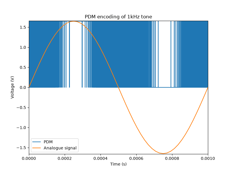
A single cycle of a 1kHz sine wave encoded using PDM
Zooming in on the pulses with the PDM sampling clock demonstrates the level of oversampling versus the original sampling frequency, assuming a conversion happens every rising clock edge:
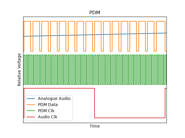
Timing diagram demonstrating the level of oversampling for PDM encoding compared to the audio sampling rate.
Decoding
The process of converting the PDM stream back to an analog audio signal is achieved by low pass filtering followed by decimation from the PDM sample rate back to the desired audio sample rate. The low pass filter has a cutoff frequency of fs / 2 so that frequencies beyond the audio sampling range are not aliased when decimating.
# Apply 3rd order Butterworth low pass filter to PDM signal
cutoff = fs / 2 # 24khz when fs=48kHz
lpf = signal.butter(3, cutoff, 'lowpass',fs=pdm_fs,output = 'sos')
z = signal.sosfilt(lpf,pdm)

# Decimate signal from pdm fs to audio fs
z = z[::fs_ratio]
The end result is shown in the plot below and compared against the original audio signal. Performing an FFT of the data shows that the frequency information is intact while the time domain plot shows that the amplitude is reconstructed in the range of the logic levels used (GND and Vref). This is expected given that the PDM encoding doesn’t consider the exact amplitude when sampling.
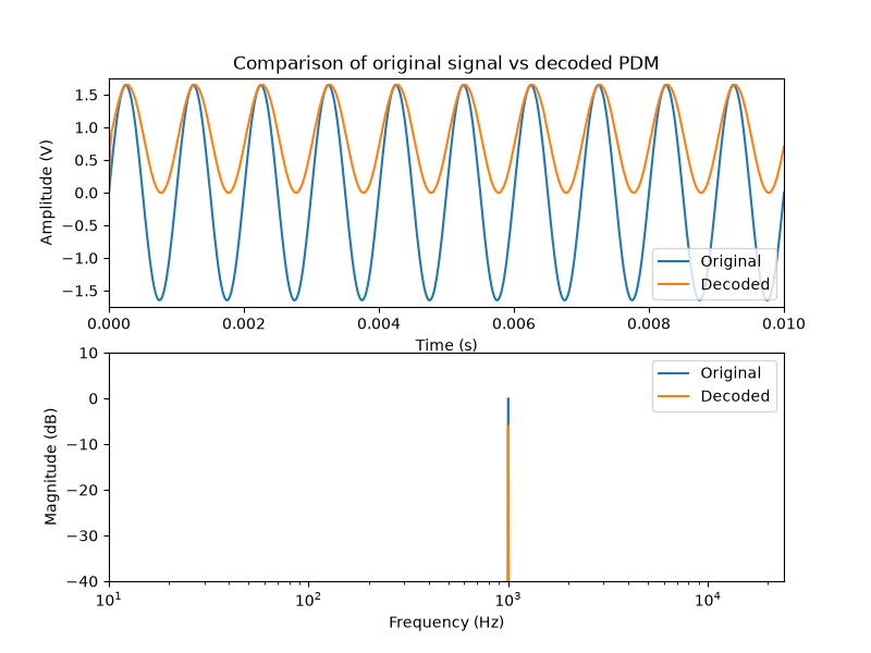
Comparison of decoded PDM audio against the original signal.
In order to remove the DC-offset so that the decoded amplitude is “centred” at 0 it may be desirable to filter the signal with a high pass filter. Here the cutoff frequency has been selected at 20Hz which is the lower limit of human hearing8.
# Apply 1st order Butterworth high pass filter to PDM signal
cutoff = 20 # Hz
hpf = signal.butter(1, cutoff, 'highpass',fs=fs,output = 'sos')
z = signal.sosfilt(hpf,z)
The end result shows that once the filter settles the DC offset has been removed:
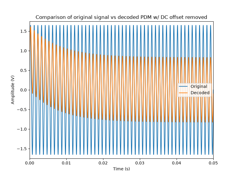
Comparison of original signal against decoded PDM with DC offset removal.
Epilogue
I highly recommend reading the technical articles provided by Analog Devices2 and Texas Instruments3 which go into significantly more technical detail about delta-sigma modulation and digitizing analogue data. It has been a useful exercise practicing the modulation and de-modulation of analogue data to the digital realm (and back again).
-
An engineer’s adventure. ↩
-
Analog Devices - ADC Architectures III: Sigma-Delta ADC Basics link ↩ ↩2 ↩3 ↩4 ↩5 ↩6 ↩7 ↩8
-
Texas Instruments - How delta-sigma ADCs work, Part 1 link ↩ ↩2 ↩3 ↩4 ↩5
-
I’ve seen this written as both Delta-sigma and Sigma-delta. ↩
-
Foundations of Digital Signal Processing: Theory, algorithms and hardware design - Professor Patrick Gaydecki. link ↩ ↩2 ↩3 ↩4 ↩5
-
In analogue circuitry this can be achieved with a difference amplifier 3. ↩