Smol Blinky
Last week I had the idea to investigate how small I could compile a .bin file that would make an LED blink. I created a repo here to manage it, but this blog will provide a more thorough explanation.
The Rules:
- Must be a single .bin file that can be flashed onto the board.
-
The blinking LED must be externally observable
This is because otherwise you could just have an infinite loop XOR’ing the LED which technically is a blink, but not really.
while(1) { /* Technically a blink but come on */ *led ^= 0x1; } - Anything else goes really.
Equipment
All I used for this was an STM32L432KC Nucleo devkit that I’ve had lying around. The devkit contains an ARM cortex m4 microcontroller along with an onboard LED (PB3). The devkit also has the ST-LINK V2 programmer built in so all I needed to do was attach a USB cable.
As far as software goes, I used the GCC arm toolchain (ld, as, objcopy and objdump) as well as openocd.
First Steps
The first step was to determine the smallest .bin file that would run successfully on the device without it crashing/hard fault/running off. This would be a simple program that simply looped indefinitely without doing anything else. Using ARM assembly, the below code snippit was what I determined to be the smallest program that would successfully execute:
    .syntax unified
    .globl _start

_start:
    .word 0xDEADBEEF
    .word _reset

.thumb_func
_reset:
    b _reset
As defined in the Cortex M4 user guide1, the vector table is at the start of the .bin file, with the first two values being the initial stack pointer value and the reset location. Here I’ve put 0xDEADBEEF as my SP value as this program is so small that it doesn’t need a stack, typically this would be something like 0x20000800 (remember that ARM uses a decrementing stack, and the RAM region starts at 0x20000000 on this chip). Using 0xDEADBEEF or some other silly value would cause the device to hard fault under a ‘normal’ program. The second word is set as _reset, which is a thumb function2 the microcontroller calls upon reset. As you can see, _reset simply contains a branch instruction to itself, which will loop indefinitely.
.syntax unified is used to signify the use of the Unified Assembler Language which is covered in more detail here3 and here4. Additionally, the global (.globl) declaration of _start (ie, the entry point) is necessary or else the linker will complain.
The below gif demonstrates the program in action (using arm-none-eabi-gdb and openocd):
Riveting stuff huh?
Assembling/Linking
First off I need to assemble the source file (smol.s), this can be done with the following command in the terminal:
$ arm-none-eabi-as -g -mcpu=cortex-m4 -mthumb smol.s -o smol.oNow that I have the object file I need to put it through the linker. Given that this is an extremely small and basic program, I can get away with placing everything in the .text section as there are no variables that would normally go in the .data or .bss regions. Given the simplicity of this program I dont even need a linker script at all, as allocating everything to the start of the read only flash region 0x08000000 can be done using the following command:
$ arm-none-eabi-ld -Ttext 0x08000000 -o smol.elf smol.o -nostdlibNow that I have the .elf file, I want to convert it to a .bin using the following instruction.
$ arm-none-eabi-objcopy -Obinary smol.elf smol.binAlright! Now that I have the .bin file, how big is it?
$ wc -c smol.bin
10 smol.bin
10 bytes, which is rather small. Lets use hexdump to see what this looks like in in the following snippit, noting the 0xDEADBEEF at the start that was placed earlier:
$ hexdump -C smol.bin
00000000  ef be ad de 09 00 00 08  fe e7                    |..........|
0000000a
So now that I know the number of bytes for the smallest runnable program on the microcontroller, how small to make an LED blink?
Blink (and you’ll miss it)
Below is my current version of the smol blinky program, which produces a binary of 40 bytes:
    .syntax unified

_start:
    /* This is where the stack top goes, but we dont
    * need a stack for this so going to repurpose it*/
    .word 0x4002104C
    /* Second word is always the reset vector */
    .word _reset
    .word 0x48000400
.globl _reset
.thumb_func
_reset:
    /* (ab)use the program counter to retrive
    * addresses stored as vectors */
    ldr r6, [pc, #-0x10]
    ldr r7, [pc, #-0x0C]

    /* Reset value for a different RCC register
    * is 0x11303, which makes a nice delay and
    * can be used to set GPIO B*/
    ldr r0, [r6, #0x1C]

    /* RCC Clock Enable Port B */
    str r0, [r6]

    /* Reuse the number stored in r6
    * to set GPIOB 3 as output */
    str r6, [r7]

delay:
    subs r0, 1
    bne delay

    /* Toggle LED */
    eor r3, r6
    str r3, [r7, #0x14]
    b _reset
hexdump + size:
$ hexdump -C smol.bin
00000000  4c 10 02 40 0d 00 00 08  00 04 00 48 5f f8 10 60  |L..@.......H_..`|
00000010  5f f8 0c 70 f0 69 30 60  3e 60 01 38 fd d1 83 ea  |_..p.i0`>`.8....|
00000020  06 03 7b 61 ff f7 f2 bf                           |..{a....|
00000028
$ wc -c smol.bin
40 smol.bin
Decomposition
Below outlines a brief explanation of how my 40 byte blinky program works.
Misusing the startup vectors
    .syntax unified

_start:
    /* This is where the stack top goes, but we dont
    * need a stack for this so going to repurpose it*/
    .word 0x4002104C
    /* Second word is always the reset vector */
    .word _reset
    .word 0x48000400
At the start of this post I explained that because the program was so small and simple, it didn’t require a stack (and thus a valid stack pointer). This means I could repurpose the register with the address of a configuration register that enables the peripheral clock for GPIO B. The word following this is the reset vector as previously discussed. I decided to repurpose a further startup vector to store the base address for GPIO B. Normally this would be the NMI handler (as per the user guide 1)
Misusing the program counter
Now that I have the necessary peripheral register addresses stored in the startup vectors, how do I access them? Lets look at the next lines in the program:
.globl _reset
.thumb_func
_reset:
    /* (ab)use the program counter to retrive
    * addresses stored as vectors */
    ldr r6, [pc, #-0x10]
    ldr r7, [pc, #-0x0C]
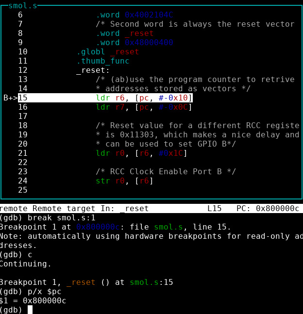
As shown in the figure below, upon a reset, the program counter (PC) will be 0x0800000c, which points to instruction ldr r6, [pc, #-0x10]. We want to load the first word in the program (at address 0x08000000) in a register so that I can use it to configure the peripheral clock for port b. This instruction loads the value stored at the location held at the program counter, with a negative offset of 0x10. You’re probably wondering why the offset is -0x10 and not instead -0x0c, what I think is happening is that when this particular instruction is undergoing the fetch-decode-execute routine, the program counter updates to 0x08000010, so the offset needs to be from this address, rather than from 0x0800000c.
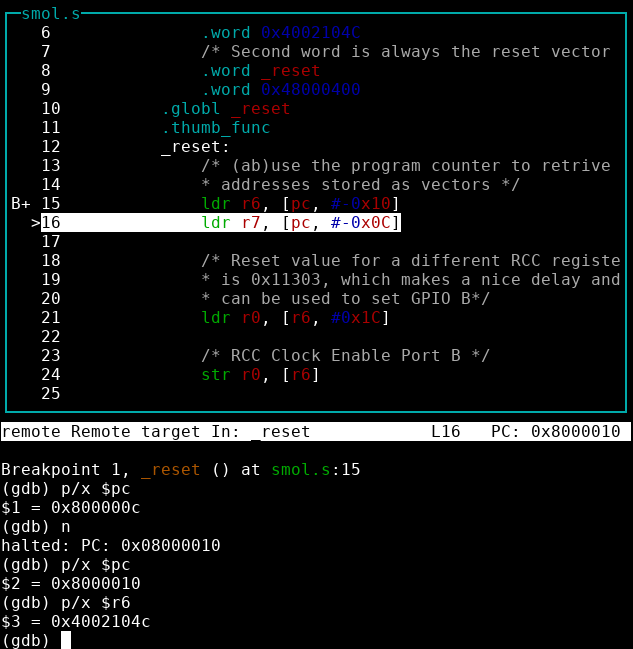
As you can see from the next screenshot, once this instruction has completed, the first word in the program has successfully been placed in register r6, and the program counter has updated to 0x80000010. A similar trick is used to copy the third vector (the base address for GPIO B) into register r7.
Configuring peripherals
    /* Reset value for a different RCC register
    * is 0x11303, which makes a nice delay and
    * can be used to set GPIO B*/
    ldr r0, [r6, #0x1C]

    /* RCC Clock Enable Port B */
    str r0, [r6]

    /* Reuse the number stored in r6
    * to set GPIOB 3 as output */
    str r6, [r7]
Before configuring the periphals so that they can blink the LED, I trawled the datasheet5 for a ‘magic’ number already prespresent on the chip that had the right bits set for:
- Enabling the peripheral clock for GPIO B
- set bit 1 of register
0x4002104c
- set bit 1 of register
- Setting PORT 3 for GPIO to be a general purpose output
- set bits 6-7 of register
0x48000400to be0x01
- set bits 6-7 of register
This would allow me to save space by having a similar number stored in the code. I found that a different RCC register (with the same base address as the one used for enable the GPIO B peripheral clock) had a default value where bit 1 was set, so I loaded this value into register r0, and then stored it at the address held in r6.
It’s worth noting that because the magic number has other bits set, it will enable a whole load of other periphals too, but I don’t particularly care for this project. In a ‘serious’ project this may have side effects!
Unfortunately this magic number did not have the necessary bits set for setting GPIOB-3 as an output. However, the address of the RCC peripheral currently held in r6 does, so this number was simply stored into the address held in r7
So now I’ve correctly configured the peripherals, all that’s left to do is to make it blink.
Blink!
delay:
    subs r0, 1
    bne delay

    /* Toggle LED */
    eor r3, r6
    str r3, [r7, #0x14]
    b _reset
The first couple of lines of this section are a simple delay, while the magic value in r0 is not zero it will continue to branch to delay, with the value decrementing by 1 each time.
In order to turn on the LED I need to set bit 3 in the value we are going to store as 1 and then store it in the output register, stored at 0x48000414. In order to clear the LED, bit 3 needs to be set to 0. I once again reuse the value stored in r6 as a magic number because it has bit 3 set to 1. This is XOR’d with the value in r3 to toggle the LED on and off every iteration.
r3 presumed to be 0 on boot, but it doesnt matter anyway
At the end of the program I branch all the way back to the beginning again, r3 is only ever used as the current LED value in this program, so it will hold its state during until it is XOR’d again.
Below is a very poorly made gif of the code in action, the LED is actually much faster but I had to reduce the framerate to make the gif a reasonable size (sorry).
Conclusion
So 40 bytes was the best I could achieve with some minor abuse of the processor. Can you do better? Let me know!