picoboard
I previously wrote about a circuit board I’d designed to facilitate environment measurements as part of a home-brew home automation system. When I tested the functionality I found that everything worked except the EEPROM which is used to hold persistent data. It transpired that I’d gotten the SDA and SCL lines on the the pad the wrong way round, woops 1. Nonetheless I quickly whipped up a fix to the design and got a new set of boards manufactured.
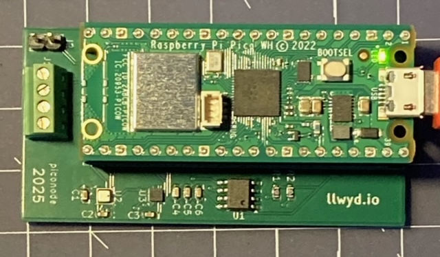
Second revision with a Raspberry Pi Pico W inserted. It looks exactly the same as the first revision other than an updated date and corrected I2C lines for the EEPROM.
Does it work? (Part II)
I followed the same test procedure as last time and found that everything worked correctly as expected.
| Functionality | Pass/Fail |
|---|---|
| BME280 Environment Sensor R/W | PASS |
| Accelerometer R/W and GPIO | PASS |
| EEPROM R/W | PASS |
| GPIO A | PASS |
| GPIO B | PASS |
| CONFIG Pin | PASS |
Demo
By shorting the CONFIG pin the user can access a basic serial console to write settings such as name, SSID etc to the EEPROM. Upon booting it also prints out some diagnostic information about the sensors and whether they can be configured correctly.
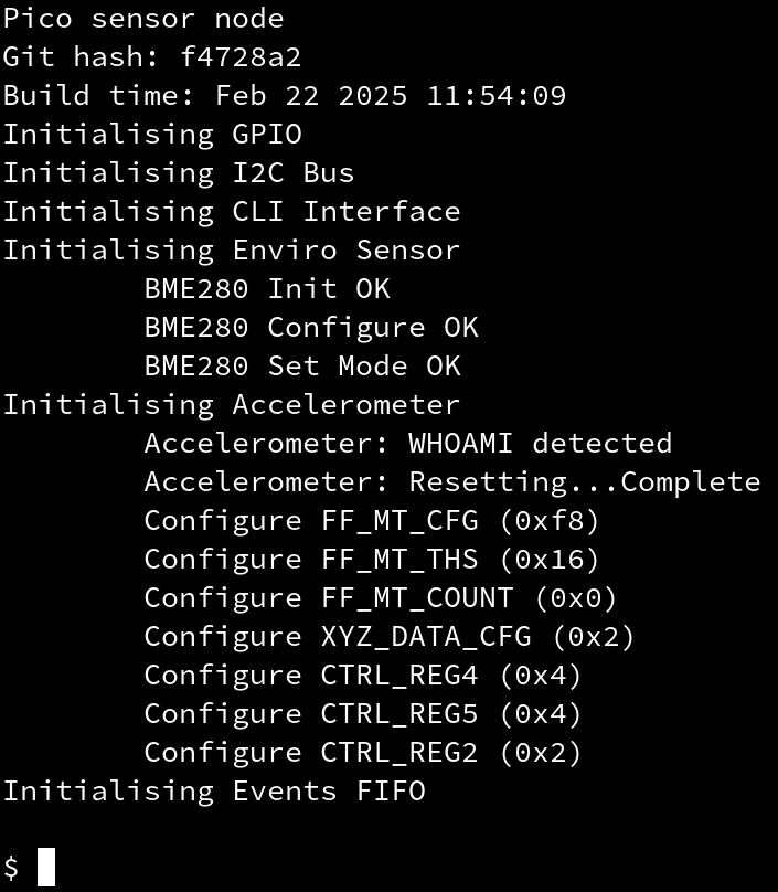
Board boots and the sensors can be configured, off to a good start
By using the commands read all and read raw I can see that the values I wrote using set <name> have been stored correctly.
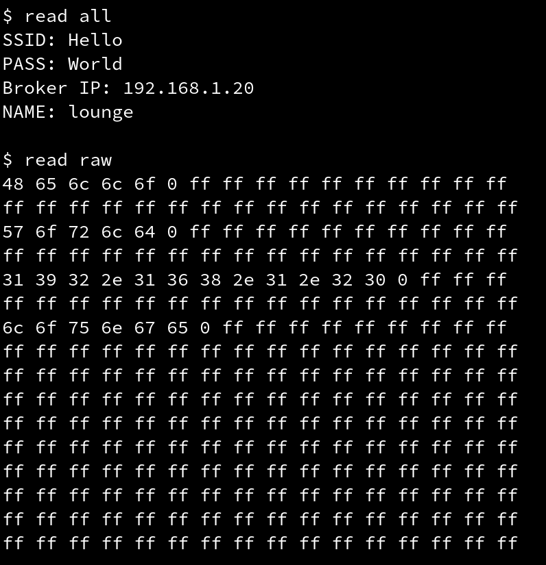
Persistent settings and raw EEPROM data
The firmware on the Pico is designed to send data using the MQTT 2 protocol to a broker. Using the mosquitto_sub tool I can peek at the incoming data and see whether it looks sensible. By subscribing to the home/environment/# topic I can see the environment data for all devices that are connected to the broker. The screenshot below shows the lounge node is transmitting a JSON payload that contains the temperature, humidity and up-time.
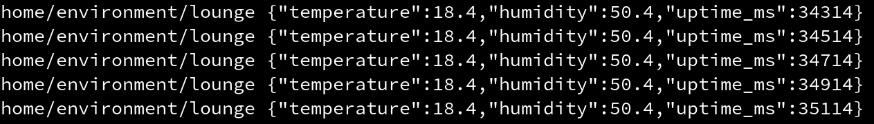
Environment data from the lounge node, transmitting every 200ms as expected
The board also has an accelerometer, which is configured to assert a GPIO line when a vibration is detected. By subscribing to home/motion/# and knocking my fist on the table I can see that the vibrations are detected and subsequent message is transmitted. The magnitude of the vibration is not necessary, as I envisioned this feature to be used as a door-knock detector.
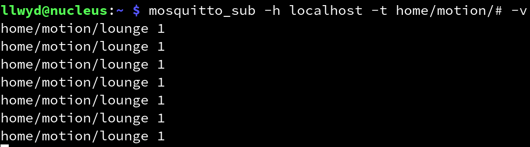
The result of smacking my fist triumphantly on the desk a few times
Finally I attached a push button to each of the GPIO inputs on the front of the board and tested to see whether a message was detected on home/gpio_a/lounge. This test was also repeated for GPIO B.
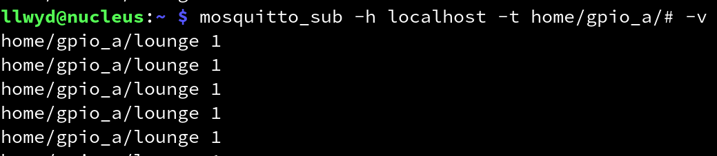
Success!
Final Schematic
The final schematic is detailed below along with a PDF version here.
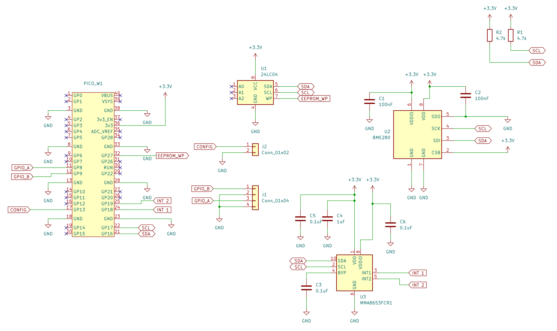
Final schematic