pinkish
As a long time Tinnitus sufferer (twenty years!) I find pink noise useful as a way to mask it or ignore it for a while. It is also useful for helping me concentrate in noisy environments such as an open plan office. I’ve written about pink noise before and how you can use the Voss-McCartney algorithm to generate it in real time1. Another method is to generate white noise (which has a flat frequency response, i.e. equal energy across all frequencies) and to filter it so that it has the characteristic -10db per decade roll-off. There are some existing IIR filter designs1,2 out there that will produce the required frequency response. I had the idea of generating pink noise using a graphic equaliser so that the resulting noise can be tweaked to personal preference.
PINKish
PINKish is a real time noise generator with 6-band graphic equaliser (EQ) that allows the listener to fine-tune the noise to their preference. The generator also has basic Automatic Gain Control (AGC)3 so that the overall volume is consistent irrespective of the EQ configuration. I developed a model of the EQ in Python so that I could manually adjust the gains to produce a pink(ish) frequency response. GitHub containing the code and the model is available here.
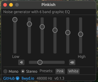
PINKish noise generator running on Mac OS. graphic design GUI layouts are my passion.4
The signal processing chain is summarised in the following diagram:
Signal processing flowchart for PINKish
Crossover Filters
The equaliser was implemented as a series of digital ‘Linkwitz-Riley’ crossover filters5. They work as a pair of low pass and high pass filters that split the incoming signal into respective low / high frequency bands. Each band has a gain applied before being summed together again:
Linkwitz-Riley Crossover filter principle5.
The output of the LR crossover filter can be cascaded to further isolate higher (or lower) frequency bands. Here the output of the HPF is the input to another LR crossover filter to further split the frequency content:
Cascading Linkwitz-Riley Crossover filters.
After each crossover stage the output of the LPF goes through a gain stage and the output of the HPF becomes the input of another crossover filter. At the final crossover filter N both LPF and HPF outputs go through their respective gain stages. The output of all the gain stages are then summed to recombine all of the frequency bands to produce the output at the full bandwidth.
Filter Design
The filters used in the crossover stages are a pair of first-order digital Butterworth filters6. The SciPy library in python provides a handy function for generating the coefficients:
from scipy import signal

order = 1
cutoff = 1000
fs = 48000
lpf = signal.butter(order, cutoff, 'lowpass', fs=fs, output='sos')
hpf = signal.butter(order, cutoff, 'highpass', fs=fs, output='sos')
The output representation of the filter is set to sos, which stands for Second-Order Sections (Also known as Biquads)7. This means that the filter can be implemented efficiently as a series of second order IIR filters using the Transposed Direct Form 2 topology8,9. The impulse response of the filter can be generated by filtering a Dirac function10 as follows:
num_samples = 1024
h = signal.unit_impulse(num_samples)

lpf_out = signal.sosfilt(lpf, h)
hpf_out = signal.sosfilt(hpf, h)
This can then be analysed and graphed using an FFT11 to view the spectral properties of the filters.
Equaliser Model
I developed an interactive model of the cascaded crossover filters using Python:
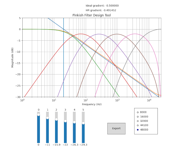
PINKish filter design tool
This model allowed me to tweak the gain sliders for each band so that the resulting frequency response in the human hearing range12 (HR) was roughly pink-ish. The plot contains an ideal 1/f frequency response as a reference as well as a real-time measurement of the gradient. The Export button auto-generates some rust code containing the filter coefficients as well as the gains for the selected sampling frequency. Python code for the model can be found here, though it is admittedly very spaghetti.
Automatic gain control (AGC)
In order to appropriately amplify or attenuate the filtered audio some measure of signal power is necessary. I run the absolute value of the filtered audio through a single pole low pass filter with a low cutoff rate (1Hz) to get a rough measure of the average power for this period13. This measure can then be compared against a desired signal power and the amplification/attenuation applied appropriately.
For PINKish a delta is calculated between the measured and desired signal power. The sign of this delta determines whether the applied gain increases or decreases:
pub struct AGC{
    set_point:f32,
    gain:f32,
}

impl AGC{
const DELTA_SCALE:f32 = 0.0005;
    pub fn new(set_point:f32) -> AGC
    {
        AGC
        {
            set_point, // Desired signal power
            gain: 0.1, // Initial Gain
        }
    }
    pub fn update(&mut self, rms:f32)
    {
        let delta = self.set_point - rms;
        self.gain *= 1.0 + (delta * Self::DELTA_SCALE);

        assert!(self.gain > 0.0);
    }
}
The DELTA_SCALE constant is necessary so that the gain doesn’t increase or decrease too quickly. If the changes in gain are too large a noticeable “pumping” sound is present which is unpleasant to listen to. After the gain is updated it is applied to the filtered signal at the next sample.
Putting it together and testing
I implemented the app in rust using cpal14 as the audio playback engine and egui15 for the user interface. The full source is available here and the audio processing loop can be found here. Upon running the program you can hear filtered noise that can be adjusted in real time using the gain sliders.
I added some command line functionality so that I could verify the signal processing was correct. Upon passing the --pink or --white flag the program will generate audio data to the console instead of the sound-card. This meant I could pipe the output to a file and analyse using python:
$ cargo run -- -w 1000 > white.txt
$ cargo run -- -p 1000 > pink.txt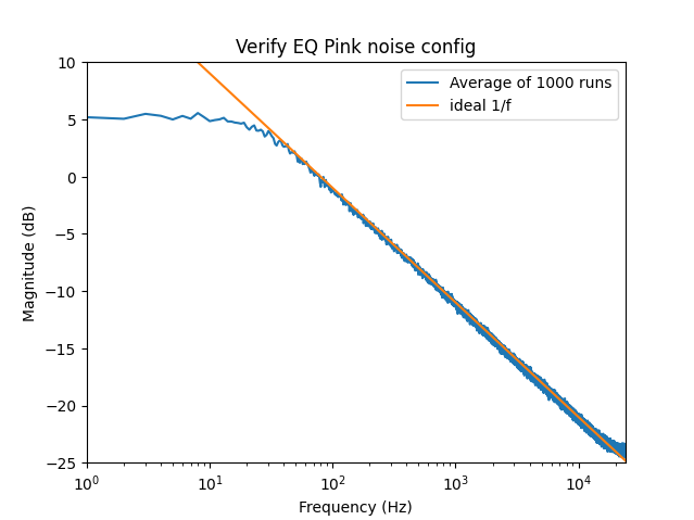
1000x 1 second samples @ 48kHz with the EQ set to ‘Pink’
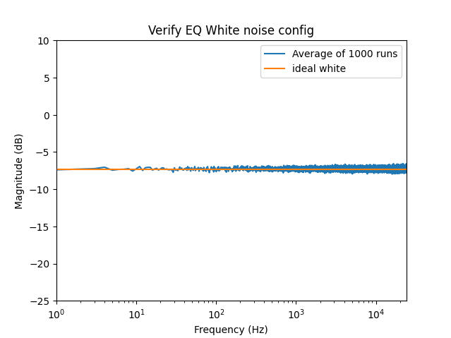
1000x 1 second samples @ 48kHz with the EQ set to ‘White’
Conclusion
While the output isn’t perfect pink noise it is nonetheless soothing to listen to in the background when I’m trying to concentrate in a noisy environment. There’s still plenty of things to improve on and I intend to keep maintaining it but it works nice as a tunable noise generator intended for human ears.
References
-
SPECTRAL AUDIO SIGNAL PROCESSING - Julius O. Smith III link ↩
-
Introduction to Digital Filters - BiQuad Section - Julius O. Smith III link ↩
-
Introduction to Digital Filters - Transposed Direct Forms - Julius O. Smith III link ↩
-
This is what SciPy is doing under the hood when using
sosfilt(), see here ↩ -
Digital Envelope Detection: The Good, the Bad, and the Ugly link ↩